
库函数解释
结构体初始化配置
void USART_DeInit(USART_TypeDef* USARTx);
void USART_Init(USART_TypeDef* USARTx, USART_InitTypeDef* USART_InitStruct);
void USART_StructInit(USART_InitTypeDef* USART_InitStruct);同步时钟配置
void USART_ClockInit(USART_TypeDef* USARTx, USART_ClockInitTypeDef* USART_ClockInitStruct);
void USART_ClockStructInit(USART_ClockInitTypeDef* USART_ClockInitStruct);发送数据
void USART_SendData(USART_TypeDef* USARTx, uint16_t Data);
- 写DR寄存器
接收数据
uint16_t USART_ReceiveData(USART_TypeDef* USARTx);
- 读DR寄存器
MicroLIB
MicroLIB是Keil为嵌入式平台优化的一个精简库
多个串口同时使用printf
char String[100];sprintf(String,"Num=%d\r\n",666);//sprintf.可以将指定的数据复制到数组中Serial_SendString(String);//打印字符串可变参数
void Serial_Prinf(char * format,...){ char String[100]; va_list arg;//参数列表变量 va_start(arg,format); vsprintf(String,format,arg); va_end(arg);//释放参数列表 Serial_SendString(String);}汉字编码发送
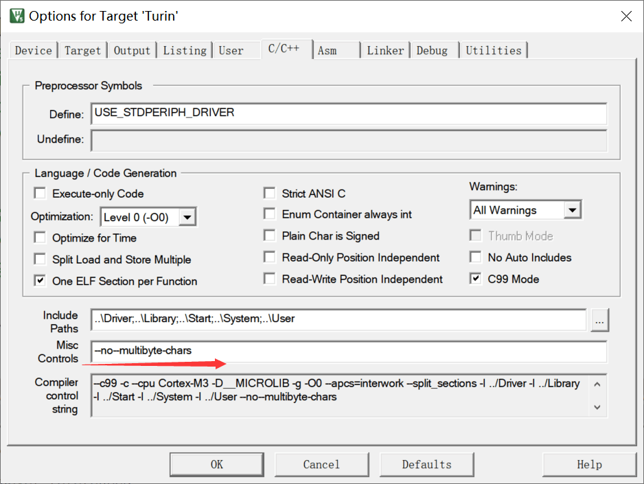
统一选定为UTF-8编码
串口接收
1.查询方法
#include <stm32f10x.h> //Device header#include <OLED.h>#include <Delay.h>#include <Serial.h>
uint8_t RXData;
int main(void){ OLED_Init();
Serial_Init();
while(1) { if(USART_GetFlagStatus(USART1,USART_FLAG_RXNE)==SET) { RXData=USART_ReceiveData(USART1);//读DR可以自动清除标志位 OLED_ShowHexNum(1,1,RXData,2); } }}2.中断方法
子程序
#include "stm32f10x.h" // Device header#include <stdio.h>#include <stdarg.h>
uint8_t Serial_RxData;uint8_t Serial_RxFlag;
void Serial_Init(void){ RCC_APB2PeriphClockCmd(RCC_APB2Periph_USART1,ENABLE); //开启USART1的时钟 RCC_APB2PeriphClockCmd(RCC_APB2Periph_GPIOA,ENABLE); //开启GPIOA的时钟
/*配置PA9为复用推挽输出,供USART1的TX使用*/ GPIO_InitTypeDef GPIO_InitStructure; //结构体类型(已经定义好的) 结构体变量名 ->结构体变量的定义
/*串口发送引脚部分*/ GPIO_InitStructure.GPIO_Speed=GPIO_Speed_50MHz; GPIO_InitStructure.GPIO_Pin=GPIO_Pin_9; GPIO_InitStructure.GPIO_Mode=GPIO_Mode_AF_PP;//复用推挽输出 GPIO_Init(GPIOA,&GPIO_InitStructure);
/*串口接收引脚部分*/ GPIO_InitStructure.GPIO_Speed=GPIO_Speed_50MHz; GPIO_InitStructure.GPIO_Pin=GPIO_Pin_10; GPIO_InitStructure.GPIO_Mode=GPIO_Mode_IPU;//上拉输入模式 GPIO_Init(GPIOA,&GPIO_InitStructure);
/*USART结构体初始化*/ USART_InitTypeDef USART_InitStructrue; USART_InitStructrue.USART_BaudRate=9600;//直接写入设定的波特率,函数内部会自动算好9600对应的寄存器配置 USART_InitStructrue.USART_HardwareFlowControl=USART_HardwareFlowControl_None;//流控制关 USART_InitStructrue.USART_Mode=USART_Mode_Rx | USART_Mode_Tx;//串口发送+接收 USART_InitStructrue.USART_Parity=USART_Parity_No;//无校验位 USART_InitStructrue.USART_StopBits=USART_StopBits_1;//1位停止位 USART_InitStructrue.USART_WordLength=8;//字长8位 USART_Init(USART1,&USART_InitStructrue);
/*中断配置*/ USART_ITConfig(USART1,USART_IT_RXNE,ENABLE);//开启RXNE的标志位到NVIC输出
/*NVIC配置*/ NVIC_PriorityGroupConfig(NVIC_PriorityGroup_2);//NVIC分组
NVIC_InitTypeDef NVIC_InitStructure; NVIC_InitStructure.NVIC_IRQChannel=USART1_IRQn; NVIC_InitStructure.NVIC_IRQChannelCmd=ENABLE; NVIC_InitStructure.NVIC_IRQChannelPreemptionPriority=1; NVIC_InitStructure.NVIC_IRQChannelSubPriority=1; NVIC_Init(&NVIC_InitStructure);
USART_Cmd(USART1,ENABLE);}
void Serial_SendByte(uint8_t Byte){ USART_SendData(USART1,Byte);//写入DR寄存器 while( USART_GetFlagStatus(USART1,USART_FLAG_TXE)2.主程序
#include <stm32f10x.h> //Device header#include <OLED.h>#include <Delay.h>#include <Serial.h>
uint8_t RXData;
int main(void){ OLED_Init(); OLED_ShowString(1,1,"RxData:");
Serial_Init();
while(1) { if(Serial_GerRxFlag()串口数据包
打包多字节为一个数据包,方便发送多字节的数据。将同一批的数据进行打包和分割
包头、包尾:简易通信协议
- 文本数据包
- Hex数据包
状态机的方法来接收数据包
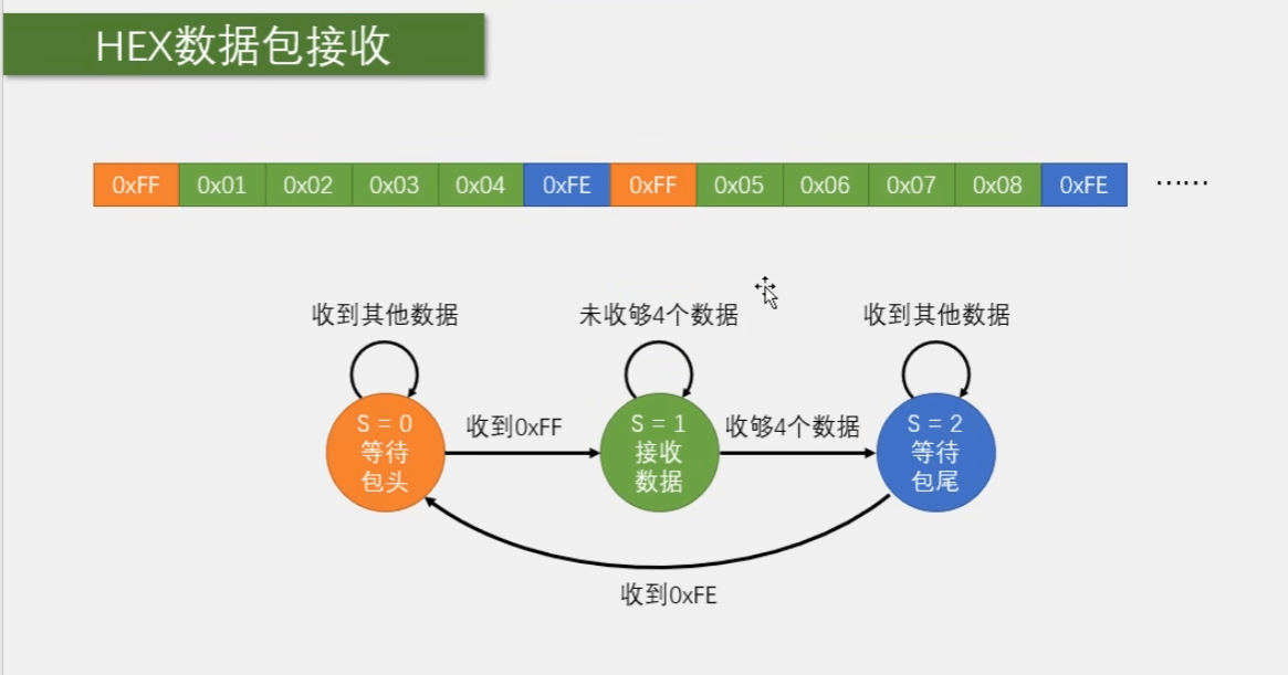
1.发送数据包
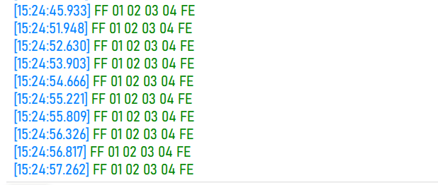
2.接收数据包
串口中断子程序
#include "stm32f10x.h" // Device header#include <stdio.h>#include <stdarg.h>
uint8_t Serial_TxPacket[4];uint8_t Serial_RxPacket[4];uint8_t Serial_RxFlag;
void Serial_Init(void){ RCC_APB2PeriphClockCmd(RCC_APB2Periph_USART1,ENABLE); //开启USART1的时钟 RCC_APB2PeriphClockCmd(RCC_APB2Periph_GPIOA,ENABLE); //开启GPIOA的时钟
/*配置PA9为复用推挽输出,供USART1的TX使用*/ GPIO_InitTypeDef GPIO_InitStructure; //结构体类型(已经定义好的) 结构体变量名 ->结构体变量的定义
/*串口发送引脚部分*/ GPIO_InitStructure.GPIO_Speed=GPIO_Speed_50MHz; GPIO_InitStructure.GPIO_Pin=GPIO_Pin_9; GPIO_InitStructure.GPIO_Mode=GPIO_Mode_AF_PP;//复用推挽输出 GPIO_Init(GPIOA,&GPIO_InitStructure);
/*串口接收引脚部分*/ GPIO_InitStructure.GPIO_Speed=GPIO_Speed_50MHz; GPIO_InitStructure.GPIO_Pin=GPIO_Pin_10; GPIO_InitStructure.GPIO_Mode=GPIO_Mode_IPU;//上拉输入模式 GPIO_Init(GPIOA,&GPIO_InitStructure);
/*USART结构体初始化*/ USART_InitTypeDef USART_InitStructrue; USART_InitStructrue.USART_BaudRate=9600;//直接写入设定的波特率,函数内部会自动算好9600对应的寄存器配置 USART_InitStructrue.USART_HardwareFlowControl=USART_HardwareFlowControl_None;//流控制关 USART_InitStructrue.USART_Mode=USART_Mode_Rx | USART_Mode_Tx;//串口发送+接收 USART_InitStructrue.USART_Parity=USART_Parity_No;//无校验位 USART_InitStructrue.USART_StopBits=USART_StopBits_1;//1位停止位 USART_InitStructrue.USART_WordLength=8;//字长8位 USART_Init(USART1,&USART_InitStructrue);
/*中断配置*/ USART_ITConfig(USART1,USART_IT_RXNE,ENABLE);//开启RXNE的标志位到NVIC输出
/*NVIC配置*/ NVIC_PriorityGroupConfig(NVIC_PriorityGroup_2);//NVIC分组
NVIC_InitTypeDef NVIC_InitStructure; NVIC_InitStructure.NVIC_IRQChannel=USART1_IRQn; NVIC_InitStructure.NVIC_IRQChannelCmd=ENABLE; NVIC_InitStructure.NVIC_IRQChannelPreemptionPriority=1; NVIC_InitStructure.NVIC_IRQChannelSubPriority=1; NVIC_Init(&NVIC_InitStructure);
USART_Cmd(USART1,ENABLE);}
void Serial_SendByte(uint8_t Byte){ USART_SendData(USART1,Byte);//写入DR寄存器 while( USART_GetFlagStatus(USART1,USART_FLAG_TXE)Serial.h
#ifndef __SERIAL_H#define __SERIAL_H#include <stdio.h>
extern uint8_t Serial_TxPacket[];extern uint8_t Serial_RxPacket[];
void Serial_Init(void);void Serial_SendByte(uint8_t Byte);void Serial_SendArray(uint8_t *Array, uint16_t Length);void Serial_SendString(char * String);void Serial_SendNumber(uint32_t Number,uint8_t Length);void Serial_Printf(char * format,...);uint8_t Serial_GetRxFlag(void);void Serial_SendPacket(void);#endif小操作
按住alt选择一列进行修改
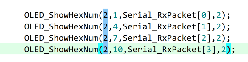
3.文本收发数据包
#include "stm32f10x.h" // Device header#include <stdio.h>#include <stdarg.h>
uint8_t Serial_RxPacket[100];uint8_t Serial_RxFlag;
void Serial_Init(void){ RCC_APB2PeriphClockCmd(RCC_APB2Periph_USART1,ENABLE); //开启USART1的时钟 RCC_APB2PeriphClockCmd(RCC_APB2Periph_GPIOA,ENABLE); //开启GPIOA的时钟
/*配置PA9为复用推挽输出,供USART1的TX使用*/ GPIO_InitTypeDef GPIO_InitStructure; //结构体类型(已经定义好的) 结构体变量名 ->结构体变量的定义
/*串口发送引脚部分*/ GPIO_InitStructure.GPIO_Speed=GPIO_Speed_50MHz; GPIO_InitStructure.GPIO_Pin=GPIO_Pin_9; GPIO_InitStructure.GPIO_Mode=GPIO_Mode_AF_PP;//复用推挽输出 GPIO_Init(GPIOA,&GPIO_InitStructure);
/*串口接收引脚部分*/ GPIO_InitStructure.GPIO_Speed=GPIO_Speed_50MHz; GPIO_InitStructure.GPIO_Pin=GPIO_Pin_10; GPIO_InitStructure.GPIO_Mode=GPIO_Mode_IPU;//上拉输入模式 GPIO_Init(GPIOA,&GPIO_InitStructure);
/*USART结构体初始化*/ USART_InitTypeDef USART_InitStructrue; USART_InitStructrue.USART_BaudRate=9600;//直接写入设定的波特率,函数内部会自动算好9600对应的寄存器配置 USART_InitStructrue.USART_HardwareFlowControl=USART_HardwareFlowControl_None;//流控制关 USART_InitStructrue.USART_Mode=USART_Mode_Rx | USART_Mode_Tx;//串口发送+接收 USART_InitStructrue.USART_Parity=USART_Parity_No;//无校验位 USART_InitStructrue.USART_StopBits=USART_StopBits_1;//1位停止位 USART_InitStructrue.USART_WordLength=8;//字长8位 USART_Init(USART1,USART_InitStructrue);
/*中断配置*/ USART_ITConfig(USART1,USART_IT_RXNE,ENABLE);//开启RXNE的标志位到NVIC输出
/*NVIC配置*/ NVIC_PriorityGroupConfig(NVIC_PriorityGroup_2);//NVIC分组
NVIC_InitTypeDef NVIC_InitStructure; NVIC_InitStructure.NVIC_IRQChannel=USART1_IRQn; NVIC_InitStructure.NVIC_IRQChannelCmd=ENABLE; NVIC_InitStructure.NVIC_IRQChannelPreemptionPriority=1; NVIC_InitStructure.NVIC_IRQChannelSubPriority=1; NVIC_Init(&NVIC_InitStructure);
USART_Cmd(USART1,ENABLE);}
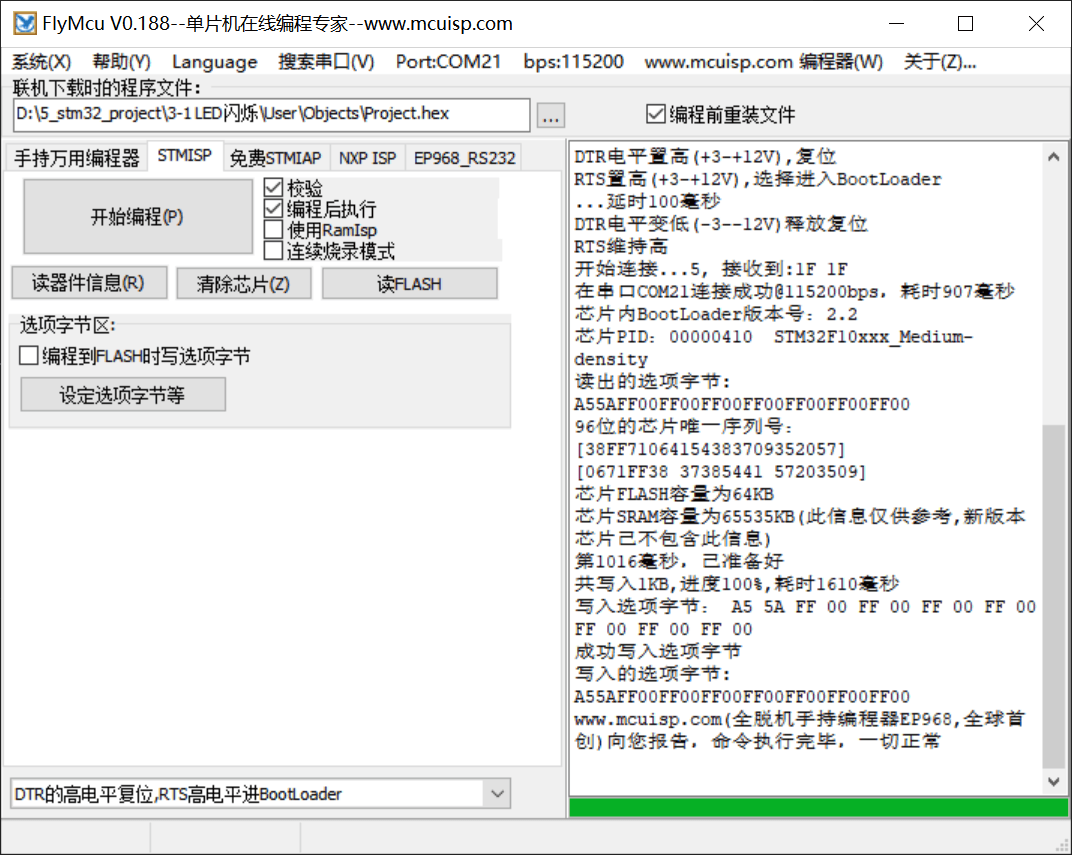
void Serial_SendByte(uint8_t Byte){ USART_SendData(USART1,Byte);//写入DR寄存器 while( USART_GetFlagStatus(USART1,USART_FLAG_TXE)串口下载
Boot引脚
BootLoder的作用相当于刷机
调试使用
可以保持跳线帽置1,但是复位后程序丢失,所以仅用来调试
读FLASH生成bin文件
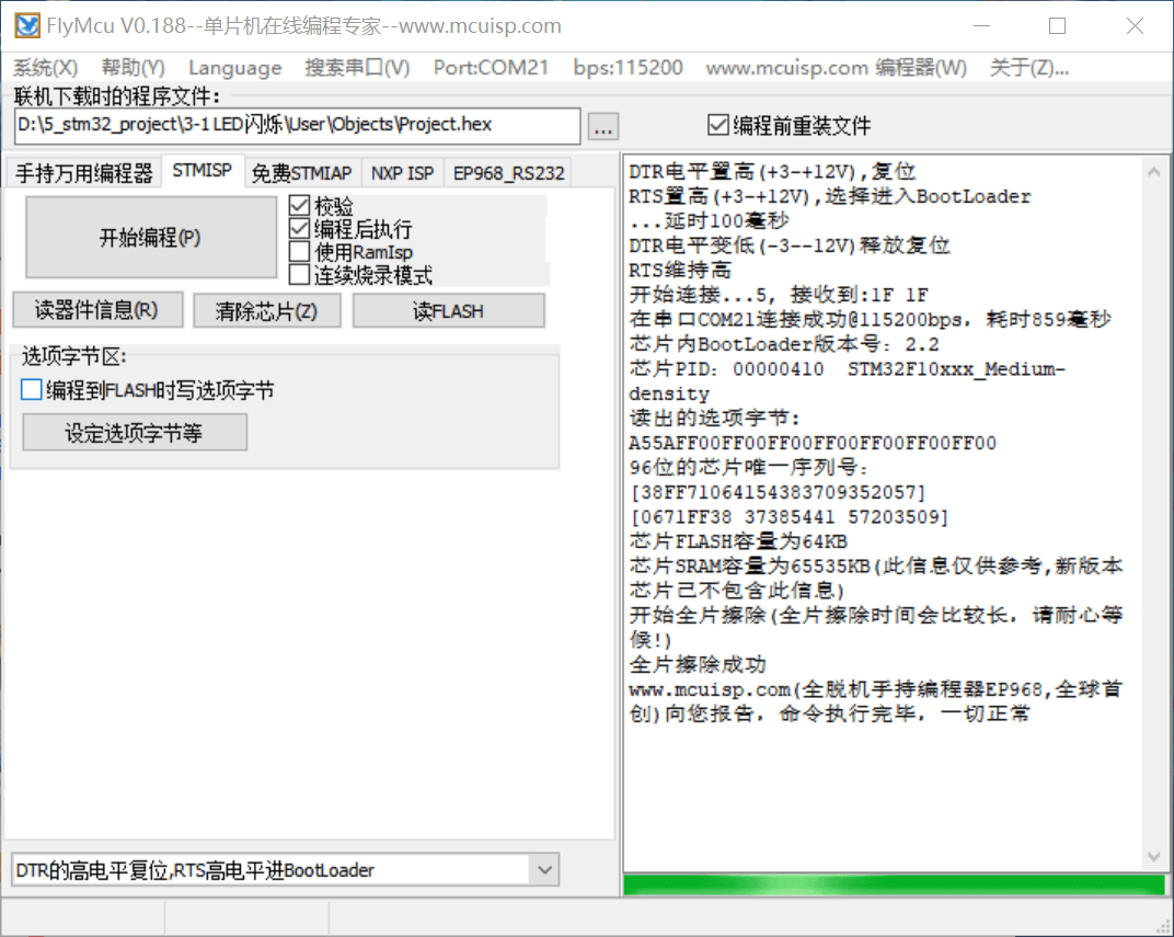
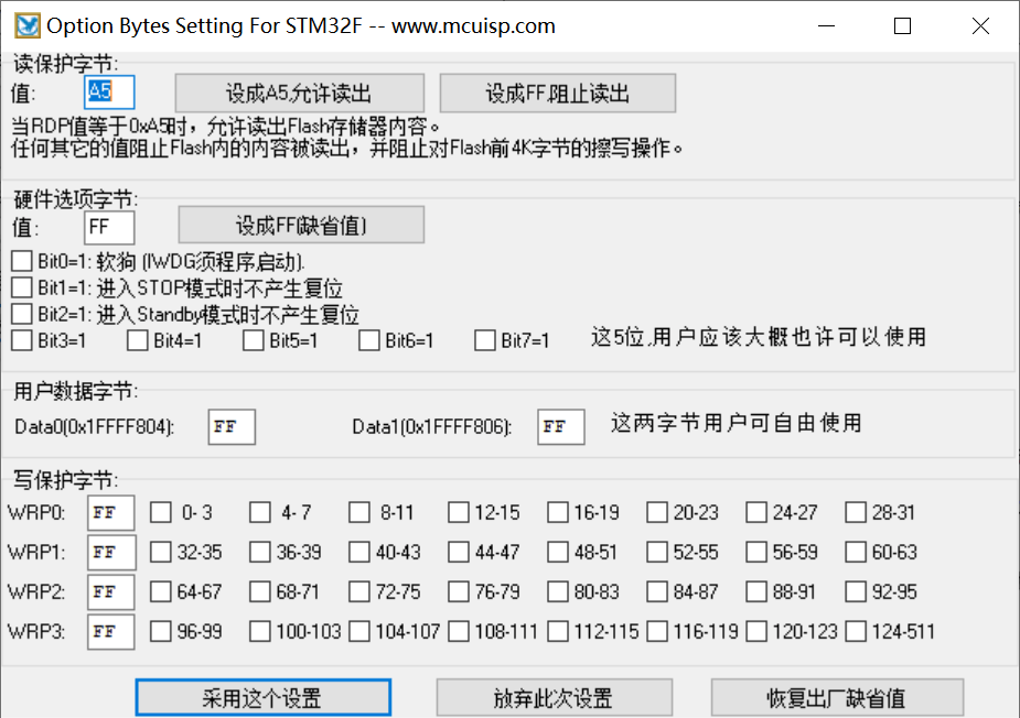
读保护/写保护
蓝牙串口通信
电赛|项目|课设:蓝牙模块HC05主从配置与连接_蓝牙 master和 slave 服务-CSDN博客
AT指令集
AT+NAME = xlg 设置蓝牙名称为xlg
AT+ROLE=0 蓝牙模式为从模式 AT+ROLE=1 蓝牙模式为主模式
AT+CMODE=0 蓝牙连接模式为任意地址连接模式
AT+PSWD=1234 蓝牙配对密码为1234
AT+UART=9600,0,0 蓝牙通信串口波特率为9600,停止位1位,无校验位
AT+RMAAD 清空配对列表
一、更改波特率
AT+UART=a,b,c
蓝牙通信串口波特率为a,
b:停止位1位,无校验位
返回响应为OK
二、修改蓝牙模块密码
修改密码的AT指令格式如下:(以修改后的密码为1314为例)
AT+PSWD=1314(这里加回车)1
三、修改蓝牙模块名字
修改模块名字的AT指令如下:
AT+NAME =1
1, AT+ROLE设置主从模式:
AT+ROLE=1是设成主,AT+ROLE=0是设成从,AT+ROLE=2设成回环模式Slave-Loop:被动连接,接收远程蓝 牙主设备数据并将数据原样返回给远程蓝牙
AT+ROLE?:查询主从状态
2, AT+RESET
3, AT+VERSION?:获取HC-05的软件版本号,只能获取,不能修改。
4, AT+ORGL:恢复出厂默认设置,当把模块设置乱了,使用此命令进行恢复默认值。
5, AT+ADDR?:获取HC-05的蓝牙地址码,只能获取,不能修改。
6, AT+NAME?:获取HC-05的名字,AT+NAME=xlg,修改模块的名字为xlg,具体名字自行修改。
7, AT+CLASS?:设置查询设备的类型,尽量不要去修改此参数。默认是1F00。
8, AT+IAC?:查询设置查询访问码,默认是9E8B33,尽量不要去修改此参数。
9, AT+PSWD?:查询设置配对密码,AT+PSWD=”0000”,密码要有双引号,密码是四位数字.
10, AT+UART:AT+UART?是查询当前模块的波特率,AT+UART=波特率,0,0。
11, AT+CMODE:AT+CMODE?是查询当前连接模式。AT+CMODE=0,1,2(0——指定蓝牙地址连接模式(指定蓝牙地址由绑定指令设置)1——任意蓝牙地址连接模式(不受绑定指令设置地址的约束)2——回环角色(Slave-Loop)默认连接模式:0)。
12, AT+BIND
13, AT+RMADD:从蓝牙配对列表中删除所有认证设备.
14, AT+STATE?:获取蓝牙模块工作状态.
15, AT+LINK=NAP,UAP,LAP:与远程设备建立连接。
16, AT+DISC:断开连接.
17, AT+RNAME?NAP,UAP,LAP:获取远程蓝牙设备名称.
18, AT+ADCN?:获取蓝牙配对列表中认证设备数。
19, AT+MRAD?获取最近使用过的蓝牙认证设备地址。
20, AT+INQM:设置查询模式,AT+INQM=1,9,48(1-带RSSI信号强度指示,9-超过9个蓝牙设备响应则终止查询,48-设定超时为48*1.28=61.44秒)
ps: HC05模块的AT指令,蓝牙命名AT+NAME= 以及密码设置AT+PSWD= 需要加双引号!